What's the best servo roll feed solution for your stamping application? Consider the HMI capabilities, available feed profiles, pilot-release mechanism, the feed-to-press mount style, and the process used to support the coil as it enters the feed.
When it comes to feeding continuous coil for progressive-die and blanking operations, metalformers must meet three basic criteria for a successful application.
• The press feed must be flexible in its setup adjustment, to accommodate the full range of material thicknesses and widths that may run in that press.
• The feed line must deliver material with sufficient precision, not only moving the required amount of material into the die but also placing it precisely right to left and front to back, and squarely to the tool.
• The feed line must index the material at the proper time, while maintaining the speed requirements of the stamping operation.
In addition to these fundamental requirements, many other considerations will ultimately determine the effectiveness of the feed line. These include the amount of time and skill required for job setup, how the feed interfaces with the operator, and how the feed interfaces with the press and other ancillary devices within the system.
Roll and Gripper Feeds—Compared and Contrasted
|
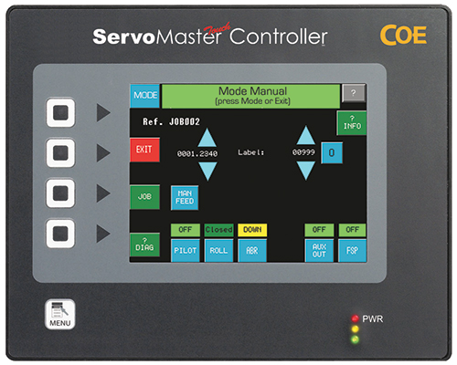
| The human-machine interface is a critical feature of servo-driven roll feeds, enabling control and communication between the operator and the press. |
Metalformers select among two basic types of feeds for indexing continuous coil—roll feeds and gripper feeds. During the last 20 years, servo-driven roll feeds have become the dominant solution for press feeding. Servo roll feeds operate independently from the press and can be programmed to index the material in a that optimizes the output of each die that runs in the press. Stampers can customize the feed recipe for each die, setting parameters such as the starting point of the index, rate of acceleration, maximum velocity, rate of deceleration and ending point of the index.
The flexibility of a servo-driven roll feed also proves beneficial, to ensure the material index occurs in the proper window of time allowed by the press, as well as other operations occurring. These include part transfer, die-protection sensing, in-die welding or assembly, and part ejection processes.
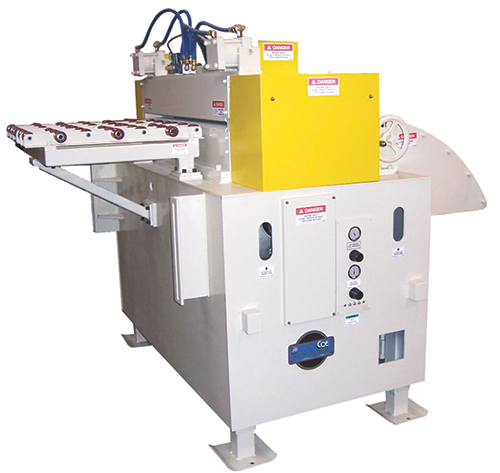 |
| Servo feed with material-support table and motorized passline-height adjustment. |
A critical feature of the servo-driven roll feed is the human-machine interface (HMI)—the device that allows the operator to program and control the servo feed, and that allows the servo feed to communicate important information back to the operator and press. Servo-feed HMIs and the associated control systems range in sophistication from simple-to-use keypads to process-specific operator interfaces, to fully flexible and programmable touchscreens. Press feed manufacturers offer varying levels of memory, communications capability, machine-setup automation and integration with the system, depending on the level of investment. Some fundamental requirements of the HMI and control system:
• Provide job memory storage;
• Allow programmable move patterns;
• Provide system troubleshooting and error reporting;
• Record batch counting and production monitoring data; and
• Allow for easy die threading through various jogging functions.
Check out these other articles.


With continued advances in servo-control technology, servo-driven roll feeds now feature a variety of move profiles to further optimize certain feeding applications. These move profiles include trapezoid-shaped, s-curve shaped and press-profile feeding.
The trapezoid-shaped profile—most commonly used—meets most application requirements and can deliver high-performance output. However, it comes with the trade-off of sharp velocity transitions, called “jerk points.” These jerk points occur at the beginning, middle and end of each index of the coil strip as the feed transitions between the acceleration, velocity and deceleration portions of its move profile. This can cause slight witness marks on the material, unacceptable in some cosmetic nonmarking applications.
To avoid witness marking, metalformers can use s-curve acceleration move profiles. Here, the feed makes gradual transitions in velocity, with high acceleration and deceleration in the interim. This profile avoids jerk points and the increased potential for material damage.
Press-profile feeds are electronically geared to the press so that the feeder acceleration and velocity follow the press as it quickens or slows. These feeds require an additional feedback device, such as an encoder or resolver, mounted to the press crank to monitor press rotation and speed.
No Discussion of Press Feeding Would be Complete
…without mentioning pilot release— the act of momentarily releasing the strip so it can be aligned by the pilot pins in a progressive or blanking die. The pilot pins correct for slight misfeeds by pulling the material into final position for forming or blanking. This momentary release helps to relieve built-up stress and binding of the strip through the feed and die due to misalignment or camber. It also alleviates potential “walking” problems of the coil strip as it moves through the die.
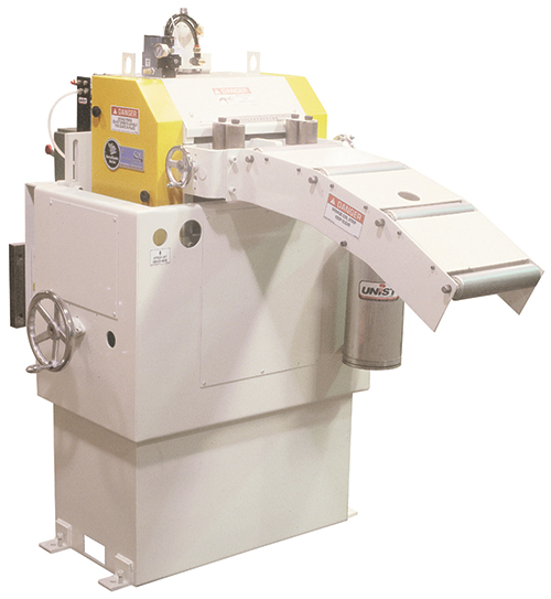 |
| Servo feed with cabinet and self-centering edge guides. |
Most servo-driven roll feeds include an air-operated pilot-release mechanism. To optimize pilot-release timing and performance, also select a mechanism with adjustable stroke. Correct timing of the roll opening and closing is critical to a successful pilot release—made easier if it’s easily adjusted for each tool.
Modern press controls typically use programmable cams to optimize the feed window and the pilot-release window for each die. Air-operated pilot-release mechanisms have a limited speed capability, although some units can attain speeds to 300 strokes/min. Some manufacturers offer servo-driven pilot release, an expensive feature but one that offers the advantage of being completely programmable and capable of very high speeds.
Other basic considerations for any press-feeding application include the servo-feed mounting method, the material support system and the material guiding mechanism. These all contribute to the overall capability and effectiveness of the press-feeding system.
The three most common mounting methods for a servo roll feed are fixed-press mounting, adjustable-height mounting brackets, and floor-standing machine cabinets. For smaller servo feeds and more dedicated feeding applications, metalformers typically opt for fixed-press mounting—the most economical and practical solution. Here the feed bolts directly to the press; passline-height adjustment must be done after manually unbolting the machine and supporting the weight of the servo feed.
Press-mounted adjustable-height brackets offer the same floorspace savings, while also providing support of the servo feed—stampers adjust passline height with a hydraulic or screw jack, no tools required. Lastly, floor-standing machine cabinets typically find use for larger machines or for applications requiring ancillary equipment such as shears, oilers, or material-support tables to be mounted to the servo feed. Cabinets typically are provided with motorized passline-height adjustment and no-tool press-mounts.
Material Support and Guidance
The catenary section is the mechanism used to support the continuous coil as it enters the servo roll feed. In conventional coil lines where the material is straightened ahead of the servo feed, the catenary section must be designed to properly support the strip as it draws from the slack loop. Lacking the necessary radius and arc of support will increase the potential to re-induce coilset or damage the material. Blanking operations, as well as certain progressive-die applications that require the incoming coil strip to be flat, can be compromised by inadequate catenary-section design.
Responsibility for material guiding in most servo roll feeds falls to the edge guide, which must maintain the continuous coil strip on center and square to the feed rolls and die. Any misalignment of the strip to the feed rolls will result in tracking of the strip relative to the main axis of the feed rolls. Likewise, any misalignment of the strip to the die will increase the potential for short feed lengths and mishits.
Like the other servo-feed devices, a variety of edge guides are available to meet the application and budget requirements for each job. Manually adjusted edge guides suit simple and dedicated feed setups; handcrank-adjusted edge guides find use for lines that require frequent changes in material width; and motorized and encoded edge guides often are used to free the operator from having to make these adjustments for each setup. MF